Dynamic Recompilation Part 4
If at first you don’t succeed, lower your standards.
Introduction
In this part we’re actually going to recompile three MIPS instructions; ADDU, SUBU and ADDIU.
We’re going to discuss a couple of basic techniques for achieving this and then discuss why they’re both suboptimal and how, if we were writing something a bit more advanced, we could do better.
Recap
Last time we got as far as being able to fall back to calling a corresponding Interpreter function
R3051 processor;
processor.WriteRegister(1, 100);
processor.WriteRegister(2, 72);
const uint32_t opcode = 0x00221821u; // ADDU R3, R1, R2

CodeBuffer buffer(1024);

EmitterX64 emitter(buffer);
emitter.PushR64(RBP);
emitter.MovR64R64(RBP, RSP);

CallInterpreterFunction(emitter, AddressOf(InterpretAddu), processor, opcode);

emitter.MovR64R64(RSP, RBP);
emitter.PopR64(RBP);
emitter.Ret();

buffer.Protect();
buffer.Call();
which means that we’ve pretty much reached that standard necessary for a Threaded Interpreter.
So that we don’t have to keep referring back to the previous part we’ll also restate the instruction encoding for ADDU.
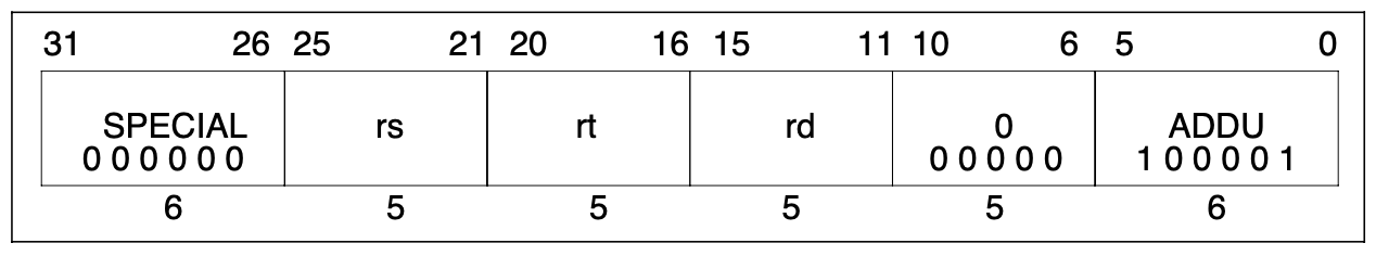
Lost in Translation
There’s nothing wrong with what we just did, but it means that there’s still a fair amount of overhead for each single instruction. The emitted CALLs will result in extra stack manipulations and the Interpreted functions themselves will do redundant work decoding the constant instruction fields each and every time.
For simple instructions like ADDU we can eliminate both forms of overhead.
At recompile time we can already deduce the values of Rs, Rt and Rd with the help of the functions
uint32_t InstructionRd(uint32_t);
uint32_t InstructionRt(uint32_t);
uint32_t InstructionRs(uint32_t);
What we are currently lacking however are a couple of abstractions in our Emitter that would let us achieve something like
MOV RAX, MIPS register Rs
MOV RCX, MIPS register Rt
ADD RAX, RCX
MOV MIPS register Rd, RAX
that is to say the ability to load a MIPS Guest Register into an x86–64 Host Register and vice-versa.
We start with observation that if we know the address of a Guest Register in memory then we can load it into a Host Register with a Move instruction.
Let’s add the following method to our R3051 class
uintptr_t RegisterAddress(uint32_t) const;
which will allow us, given a register number, to return the address of that register in memory. Its implementation for now is as follows
uintptr_t R3051::RegisterAddress(uint32_t r) const {
return reinterpret_cast<uintptr_t>(®isters[r]);
}
Now that we know how to get the address of a Guest Register in memory we would like to be able to transfer it to and from a Host Register. Consulting the Intel Software Developer’s Manual12 gives us two plausible options for a naive implementation:
MOV EAX,moffs32* ; (A1)
MOV moffs32*,EAX ; (A3)
Note that we’re only interested in loading 32-bit quantities to and from RAX since the MIPS registers themselves are 32-bit. So let’s add these two functions to our Emitter.
void EmitterX64::MovEAXAbs(uintptr_t address) {
    // MOV eax, address
    buffer.Byte(0xA1u);
    buffer.QWord(address);
}

void EmitterX64::MovAbsEAX(uintptr_t address) {
    // MOV address, EAX
    buffer.Byte(0xA3u);
    buffer.QWord(address);
}
There is just one problem with this approach in that we can only move data in and out of RAX. If you recall in the above assembly outline we wanted to load one of the operands into RCX, so we’re also going to need the ability to move quantities between Host Registers.
After further consultation of the Intel manual we can arrive at
void EmitterX64::MovR32R32(uint32_t rm, uint32_t reg) {
    // MOV rm, reg
    const uint8_t rex = Rex(0, reg >> 3u, 0, rm >> 3u);
    const uint8_t mod = ModRM(3u, reg, rm);
    buffer.Bytes({ rex, 0x89u, mod });
}
which will let us move 32-bit quantities around between the Host Registers (in this case from RAX to RCX).
Of course, we would like to be able to Add our two 32-bit values together, so we will need to emit the actual Add instructions on the Host
void EmitterX64::AddR32R32(uint32_t rm, uint32_t reg) {
    // ADD rm, reg
    const uint8_t rex = Rex(0, reg >> 3u, 0, rm >> 3u);
    const uint8_t mod = ModRM(3u, reg, rm);
    buffer.Bytes({ rex, 0x01u, mod });
}
Putting this all together we get
void EmitAddu(EmitterX64& emitter, R3051& processor, uint32_t opcode) {
    // Rd = Rs + Rt
    const uint32_t rs = InstructionRs(opcode);
    const uint32_t rt = InstructionRt(opcode);
    const uint32_t rd = InstructionRd(opcode);
    emitter.MovEAXAbs(processor.RegisterAddress(rs));
    emitter.MovR32R32(RCX, RAX);
    emitter.MovEAXAbs(processor.RegisterAddress(rt));
    emitter.AddR32R32(RAX, RCX);
    emitter.MovAbsEAX(processor.RegisterAddress(rd));
}

R3051 processor;
processor.WriteRegister(1, 100);
processor.WriteRegister(2, 72);
const uint32_t opcode = 0x00221821u; // ADDU R3, R1, R2

CodeBuffer buffer(1024);

EmitterX64 emitter(buffer);
EmitAddu(emitter, processor, opcode);
emitter.Ret();

buffer.Protect();
buffer.Call();
Again we can verify this works with some help from our IDE
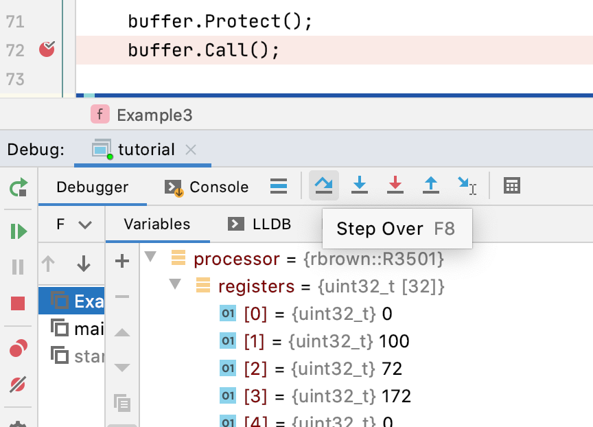
but what’s of greater interest is the disassembly
->  0x10f37000c: movabsl 0x7ffee08afa24, %eax
0x10f370015: movl   %eax, %ecx
0x10f370018: movabsl 0x7ffee08afa28, %eax
0x10f370021: addl   %ecx, %eax
0x10f370024: movabsl %eax, 0x7ffee08afa2c
0x10f37002d: ...
which is more-or-less what we expect, but we should draw our attention to the fact that each of those MOVABSL instructions is 9 bytes long and the entire segment is 33 bytes long.
Let’s see if we can do better in the next section.
Relatively Speaking
Up until this point we’ve been using Absolute Addressing, that is to say we know absolutely where each individual Guest Register is in memory and leveraged this information to write our Dynamic Recompiler.
There is however another form of addressing called Register Indirect with Displacement supported by x86–64 processors which might help us produce shorter code.
Register Indirect with Displacement addressing works by taking the value stored in a register, adding a displacement to that value, and then using the result to form an address with which to either read from or write to memory.
To make the example more concrete we have, in Intel syntax, the following instruction
MOV EAX, DWORD PTR [R9 + 12]
which says “Load the 32-bit quantity (signified by DWORD) at the location in memory addressed by the value in R9 plus 12 into EAX”.
That’s nice but how does this help?
Well, our Guest Registers are represented in our R3051 class as an array. This means that the registers are stored contiguously in memory. The first 4 bytes represent the first Guest Register, the next 4 the second Guest Register and so on. Therefore, if we know the Absolute Address of the first Guest Register then we know the addresses of all the other Guest Registers relative to the first.
We can use this relative location together with Register Indirect with Displacement addressing to produce shorter code.
In order to be able to use this form of addressing we’re going to have to revisit our friend the ModR/M byte. Let’s restate its definition here.
| 7 6 | 5 4 3 | 2 1 0 |
|---|---|---|
| mod | reg | rm |
So far, we’ve been setting both mod bits to 1. In most cases, this tells the processor that the mod and rm fields represent registers directly.
However, when we set the mod bits to something other than both 1 then the processor interprets the meanings of the mod and rm fields differently3. When mod is
- 00 we’re telling the processor to use the value in the rm register indirectly as an address.
- 01 we’re telling the processor to use the value in the rm register with a signed 8-bit displacement indirectly as an address.
- 10 we’re telling the processor to use the value in the rm register with a signed 32-bit displacement indirectly as an address.
Note: This isn’t the entire story. When rm is one of RSP, RBP, R12 or R13 then the processor will use different forms of addressing. Use with care!
Which value of mod do we want to use?
It turns out that our Guest Register array in the R3051 class is 128 bytes long and that the last Guest Register is 124 bytes away from the first. 124 can be represented by a signed 8-bit quantity, so we want to use 01. Knowing this we can now introduce the following two methods to our Emitter class
void EmitterX64::MovR32Disp8(uint32_t reg, uint32_t rm, uint8_t disp8) {
    // MOV reg, DWORD PTR [rm + disp8]
    const uint8_t rex = Rex(0, reg >> 3u, 0, rm >> 3u);
    const uint8_t mod = ModRM(1u, reg, rm);
    buffer.Bytes({ rex, 0x8Bu, mod, disp8 });
}
and
void EmitterX64::MovDisp8R32(uint32_t rm, uint8_t disp8, uint32_t reg) {
    // MOV DWORD PTR [rm + disp8], reg
    const uint8_t rex = Rex(0, reg >> 3u, 0, rm >> 3u);
    const uint8_t mod = ModRM(1u, reg, rm);
    buffer.Bytes({ rex, 0x89u, mod, disp8 });
}
to move 32-bit quantities in and out of registers respectively.
We can now put this all together to get
void EmitAddu(EmitterX64& emitter, R3051& processor, uint32_t opcode) {
    // Rd = Rs + Rt
    const uint32_t rs = InstructionRs(opcode);
    const uint32_t rt = InstructionRt(opcode);
    const uint32_t rd = InstructionRd(opcode);
    const size_t size = sizeof(uint32_t);
    emitter.MovR64Imm64(RDX, processor.RegisterAddress(0));
    emitter.MovR32Disp8(RAX, RDX, rs * size);
    emitter.MovR32Disp8(RCX, RDX, rt * size);
    emitter.AddR32R32(RAX, RCX);
    emitter.MovDisp8R32(RDX, rd * size, RAX);
}

R3051 processor;
processor.WriteRegister(1, 100);
processor.WriteRegister(2, 72);
const uint32_t opcode = 0x00221821u; // ADDU R3, R1, R2

CodeBuffer buffer(1024);

EmitterX64 emitter(buffer);
emitter.PushR64(RBP);
emitter.MovR64R64(RBP, RSP);

EmitAddu(emitter, processor, opcode);

emitter.MovR64R64(RSP, RBP);
emitter.PopR64(RBP);
emitter.Ret();

buffer.Protect();
buffer.Call();
The important line is
emitter.MovR64Imm64(RDX, processor.RegisterAddress(0));
which moves the address of the first Guest Register into the scratch register RDX so that it can be used as a base register for computing the relative addresses of the Guest Registers.
Let’s look at the disassembly
->  0x10e71000a: movabsq $0x7ffee150fa20, %rdx
0x10e710014: movl   0x4(%rdx), %eax
0x10e710018: movl   0x8(%rdx), %ecx
0x10e71001c: addl   %ecx, %eax
0x10e71001f: movl   %eax, 0xc(%rdx)
0x10e710023: ...
This segment is 25 bytes long and while that doesn’t look like that much of an initial saving at first, if we were to store the address of the first Guest Register permanently in RDX across multiple ADDU instructions then we would only emit 15 bytes per instruction.
That’s quite an improvement!
Just Keep Swimming
We have thus far been focusing on getting something that works. But there are some obvious drawbacks that should be pointed out.
Consider the MIPS instruction
ADDU R1, R3, R3
As it stands our recompiler will fetch the Guest Register R3 from memory twice. This is unnecessary work. We could fix this by making our EmitAddu function a bit smarter but that won’t address this second case
ADDU R1, R3, R4
ADDU R2, R3, R4
Again, the example is a little contrived, but across the two instructions we will fetch Guest Registers R3 and R4 from memory twice in very short succession when we could have done better to have held those values in Host Registers. Our recompiler is very forgetful.
To combat this forgetfulness, how about we store all the MIPS registers in the x86–64 registers instead? Do we really need to do all this extra work?
Well the problem with this approach is that MIPS processors have 32 registers and x86–64 processors have 16 registers. We simply can’t keep all the Guest Registers in Host Registers the entire time.
This problem is called Register Allocation4 and would be worthy of its own series of articles. For now, we’ll continue with our forgetful approach because there are other things related to the MIPS family that need to be covered before going for the bells and whistles.
The Others
In this final section we’ll cover the two other MIPS instructions SUBU and ADDIU.
SUBU should now offer little in the way of surprises. We can use most of the heavy lifting we did for ADDU. We’ll need a way to tell the Host Processor to subtract two 32-bit registers from one another. We can extend the Emitter class further with
void EmitterX64::SubR32R32(uint32_t rm, uint32_t reg) {
    // SUB rm, reg
    const uint8_t rex = Rex(0, reg >> 3u, 0, rm >> 3u);
    const uint8_t mod = ModRM(3u, reg, rm);
    buffer.Bytes({ rex, 0x29u, mod });
}
Our EmitSubu method would look something like
void EmitSubu(EmitterX64& emitter, R3051& processor, uint32_t opcode) {
    // Rd = Rs - Rt
    const uint32_t rs = InstructionRs(opcode);
    const uint32_t rt = InstructionRt(opcode);
    const uint32_t rd = InstructionRd(opcode);
    const size_t size = sizeof(uint32_t);
    emitter.MovR64Imm64(RDX, processor.RegisterAddress(0));
    emitter.MovR32Disp8(RAX, RDX, rs * size);
    emitter.MovR32Disp8(RCX, RDX, rt * size);
    emitter.SubR32R32(RAX, RCX);
    emitter.MovDisp8R32(RDX, rd * size, RAX);
}
ADDIU requires a little more thought. It’s a MIPS I-Type instruction and its encoding looks like this
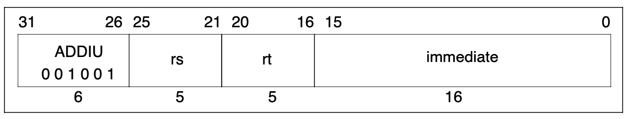
it operates by sign extending5 the immediate field to 32-bits and adding it to the value in Rs then storing the result in Rt.
The reason that this requires a little more thought is that x86–64 processors only really support 8-bit and 32-bit immediate values. They have an Operand Size Override Prefix (0x66u) to let you use 16-bit immediate values but the consensus appears to be that we should avoid using it.
At recompile time we can sign extend the constant immediate value to 32-bits ourselves with the help of this function.
uint32_t InstructionImmediateExtended(uint32_t);
Next, we want to be able to add a 32-bit immediate quantity to a 32-bit register. Consulting the Intel manual once more we can then extend our Emitter with
void EmitterX64::AddR32Imm32(uint32_t rm, uint32_t imm32) {
    // ADD rm, imm32
    const uint8_t rex = Rex(0, 0, 0, rm >> 3u);
    const uint8_t mod = ModRM(3u, 0, rm);
    buffer.Bytes({ rex, 0x81u, mod });
    buffer.DWord(imm32);
}
The EmitAddiu function would then look like
void EmitAddiu(EmitterX64& emitter, R3051& processor, uint32_t opcode) {
    // Rt = Rs + Imm
    const uint32_t rs = InstructionRs(opcode);
    const uint32_t rt = InstructionRt(opcode);
    const uint32_t immediate = InstructionImmediateExtended(opcode);
    const size_t size = sizeof(uint32_t);
    emitter.MovR64Imm64(RDX, processor.RegisterAddress(0));
    emitter.MovR32Disp8(RAX, RDX, rs * size);
    emitter.AddR32Imm32(RAX, immediate);
    emitter.MovDisp8R32(RDX, rt * size, RAX);
}
which loads Rs into RAX and then adds the immediate sign extended quantity to it.
Now that we can finally recompile more than one type of instruction it would be perhaps helpful to have a function like
void Emit(EmitterX64& emitter, R3051& processor, uint32_t opcode) {
    switch (InstructionOp(opcode)) {
        case 0x00: switch(InstructionFunction(opcode)) {
                case 0x21: return EmitAddu(emitter, processor, opcode);
                case 0x23: return EmitSubu(emitter, processor, opcode);
                default:
                    break;
            }
        case 0x09: return EmitAddiu(emitter, processor, opcode);
        default:
            break;
    }
}
to decode the instruction types and dispatch them to the appropriate recompilation method. This looks very much like the interpreter loop we presented all the way back in Part 1.
Conclusion
In this article we implemented two versions of the ADDU instruction and discussed their shortcomings.
We also drew attention to the fact that our naive and somewhat forgetful implementation could be improved upon by using Register Allocation.
Finally, we implemented two other instructions SUBU and ADDIU by building upon what we learned.
In the next part we’ll implement the ADD instruction and talk about MIPS exceptions.